Download Program At90s2313 With Arduino Mega
How to program an ATMEGA2560 with an Arduino UNO/MegaHi. This is just a reference guide that i made motivated by the lack of clear information around Internet in the matter of programming an stand-alone Atmel ATMEGA chip different from the 'standard' ATMEGA 328P-PU found in the Arduino UNO board.While it is true that you can find all this information in other websites ( i will try to mention all of them here, too ), none of them clearly explain, step by step, how to do it without other external hardware programmers or special software. So, here we go.Hardware requirements.
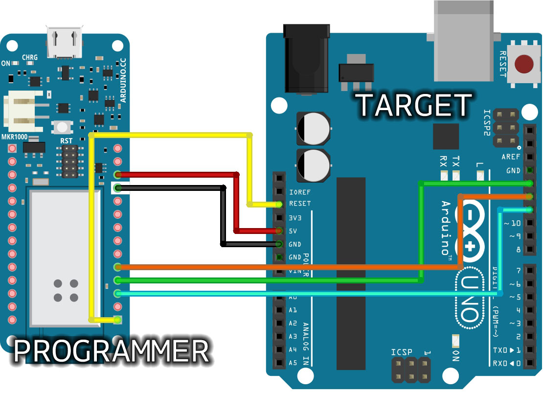
The chip, in this case an ATMEGA 2560, with the basic components for it to work: a 16Mhz oscillator and two 22pF capacitors. Optionally and also usually recommended, a 10K resistor for the reset pin. An Arduino UNO or Arduino Mega. Will work with other boards, but i only have those ones.Software requirements. Arduino IDE. A text editorWiringThe wiring is pretty simple and is already explained in the ArduinoISP sketch. Apart from the oscillator ( connected to XTAL1 and XTAL2 ), capacitors (connected to each XTAL and to the GND ) and resistor ( connected to the RESET and VCC ), connect the following depending on the board ( UNO or Mega )NameATMEGA 2560 PINToArduino UNO PINOrArduino Mega PINReset30=10/53MOSI21=11/51MISO22=12/50SCK20=13/52GNDGND=GND/GND+5VVCC=VCC/VCCProgramming the bootloaderThe first step is clear.
Assuming that our ATMEGA2560 is empty, we will program the Arduino bootloader. This step is, in fact, optional, since the chip could be programmed with our sketch directly, but the Arduino bootloader eases the process of reprogramming by using only the serial RX/TX ports.Start the Arduino IDE program. Connect just the Arduino UNO / Arduino Mega, and load the File - Examples - ArduinoISP sketch.Select the appropiate board under Tools and the default AVR ISP mkII as programmer. Select the serial port and finally compile and upload the sketch as you would normally do.Now that we programmed our Arduino with the ArduinoISP, it's time to program our litlle chip.Disconnect the Arduino and proceed to connect the previous wiring PINs.
Then reconnect the Arduino board.Find the file called 'boards.txt' located in your Arduino installation directory. In my case, the path is 'arduino-1.6.5/hardware/arduino/avr/boards.txt'.
Open it with your favourite text editor and locate the ATMEGA2560 section.The key line is the following: mega.menu.cpu.atmega2560.bootloader.highfuses=0xD8We have to replace the value of '0xD8' with '0xD9'. This is so, because in stand-alone ATMEGA2560 chips, if the BOOTRST fuse is not set, the chip will be correctly programmed, but the programs will never run.
So the line could look like this ( we can keep the original line commented ): # mega.menu.cpu.atmega2560.bootloader.highfuses=0xD8mega.menu.cpu.atmega2560.bootloader.highfuses=0xD9Save the changes and now, in our Arduino IDE program, select the Arduino Mega 2560 board and processor, the Arduino as ISP programmer and finally, from Tools, choose Burn the bootloader. If everything is done correctly, the process will take some seconds and will finish with no errors. BalloonGuy3 years, 10 months agoHello,Thank you very much for this tutorial, there are very few out there that talk about programming an ATMEGA2560 standalone chip.Like you stated, I've used ICSP to upload code to my ATMEGA2560 chip (I'm using it with an 8 MHz external crystal to get Vcc to 3.3 V). However, like you said above, if I don't change the boards.txt fuse to 0xD9, it looks like the program is uploading but nothing is happening (I'm uploading a simple blink function). However, when I try to change the boards.txt file, I get the following error:'Property line '?# See: in file C:Program Files (x86)Arduinohardwarearduinoavrboards.txt is invalidError compiling for board Arduino/Genuino Uno.' (I'm using the Uno as the programmer). Do you have any idea why this is happening and any suggestions to go about this?Thanks again!.
Download Program At90s2313 With Arduino Mega Download
3 years, 4 months agoHi Paul,Glad to know it.

PrerequisitesIn order to follow this series of tutorials on the ATtiny2313, you will need to have some experience in the following fields. Building CircuitsIt is assumed that you have some basic knowledge of electronics and that you can build breadboard circuits. If not, learn about electronics and how to build breadboard circuits in the course.Software DevelopmentTo be able to do your own software development, you will need to be able program in the C programming language. If you do not know the C programming language, then it is still possible to follow the tutorials as you will be able to load the C program examples to the microcontroller without having to write your own programs.
Also, get the database report. Native instruments b4ii keygen free.
Hardware Requirements Electronic ComponentsAn ATtiny2313 microcontroller in a dual inline package (DIP) is needed (this package is called PDIP in the Atmel literature – Plastic Dual Inline Package). It is recommended to get the ATtiny2313 microcontroller with part number ATTINY2313-20PU.Other electronic components such as LEDs, resistors, capacitors, etc. Are also needed. The required components will be listed in each part of this tutorial as needed in each part. Breadboard and Power SupplyAn electronic breadboard and wire links are needed for building the circuits.A 5V (five volt) power supply is required for powering the circuits. The 5V from a PC power supply can be used. Hardware ToolsIn order to load a program to the ATtiny2313, a programming device is needed.
This device is connected to the USB port of a PC. The header of the programming device is then connected to certain pins of the ATtiny2313 in order to load a program to it.There are several AVR programming devices to choose from.

Some are for programming the AVR microcontroller only, but others have debugging capabilities as well. Some popular programmers are listed below. AVRISP mkIIThe is an AVR programmer from Atmel for in-system programming (ISP) of AVR microcontrollers. This programmer does not have any debugging capabilities. AVR DragonThe is an AVR programmer from Atmel for in-system programming, debugging and high-voltage programming (HV programming). HV programming is used to reset certain internal fuse bits of the AVR that ISP programmers can't reset.The AVR Dragon is a good choice of programmer as it has more capabilities than a plain ISP programmer.Be aware that the AVR Dragon is not supplied with any cables. You will need to buy a standard USB cable (not the miniature type) as well as a ribbon cable with a 6-pin (2 by 3 pin) IDC female header on each end.
That will be fine for use on this course.There are two other ribbon cables that can also be plugged into the AVR Dragon. One is for the JTAG connector which is used on some AVR microcontrollers (not the ATtiny2313) and is a 10-pin header (2 by 5 pins).
The other ribbon cable is for connecting to the 20-pin (2 by 10) HV programming header and is needed only if doing HV programming. Home Made ProgrammerThere are several AVR programmers that can be built at home (for ISP programming only, not for debugging). There is one that works from the PC parallel port and one that works from the PC serial port.

Do a search on the Internet to find these.Another home built AVR programmer that works from a USB port is the open source. You can build this programmer yourself from scratch or buy a kit and build it.These home built programmers may need other software to be loaded in order to use them and may not be able to be used directly from within the Atmel AVR Studio software that we will be using in this course. Software Requirementsversion 6.0 is the software development environment and toolchain used in this course. This course was designed and tested using Atmel Studio 6.0 running on Windows 7.Other versions of Atmel Studio and other versions of Windows should also work. Getting Set UpTo get the required software installed and to test program the hardware, follow the article on this website.This article uses the AVRISP mkII to program a ATtiny2313 microcontroller circuit that flashes an LED on and off. If you are using the AVR Dragon instead, just select the AVR Dragon in the Atmel Studio settings instead of the AVRISP mkII. For other programmers, you will need to follow their specific software requirements and usage instructions.Once you have followed the above article, you will have the software and hardware installed and tested.
You will then be ready to follow the rest of the parts of this tutorial.